Bridge Expansion Joint CAD Details BEJS Bridge Expansion Joint System
Wall or Slab Joint Isolation Detail 1. Detail Drawing (DWG) DWG - 774 KB (en) Wall or Slab Joint Isolation Detail 2. Detail Drawing (DWG) DWG - 756 KB (en) Thin Set Tile Detail. Detail Drawing (DWG) DWG - 725 KB (en) Termination Detail. Detail Drawing (DWG) DWG - 656 KB (en) Waterproofing Assembly with Utility Finish.
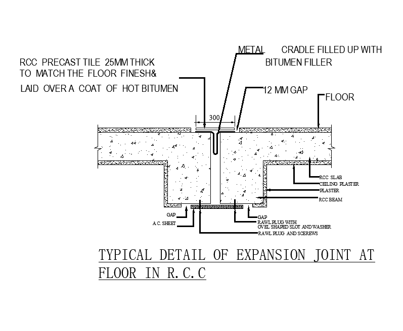
Typical detail of expansion joint at floor in rcc floor detail drawing specified in this Auto
Expansion Joint Detail. This drawing shows a typical expansion joint detail / method used when applying SL Series Joint Fillers / Sealants to a concrete substrate. Download full PDF version here. Disclaimer: This drawing is intended for information use only. Any dimensions included in this drawing are based on estimates or industry standards.

Expansion Joints Details Autocad Drawing
Title: Standard Drawing 5401 B - Concrete Pavement All Types - Expansion Joint Detail Author: VicRoads Subject: Standard Drawings Created Date: 12/3/2004 5:01:30 PM
Expansion Joint Details · BIM · CAD · DWG · DWF · Sika Emseal
Expansion Joint Transitions 3-D Designed with Inventor. Utilizing 3-D drawings early on in the design phase of the project helps translate how the expansion joint transitions are fabricated. This will also facilitate more accurate bidding by the subcontractors and ultimately a well thought-out and executed waterproof expansion joint transition.
Expansion Joint Details · BIM · CAD · DWG · DWF · Sika Emseal
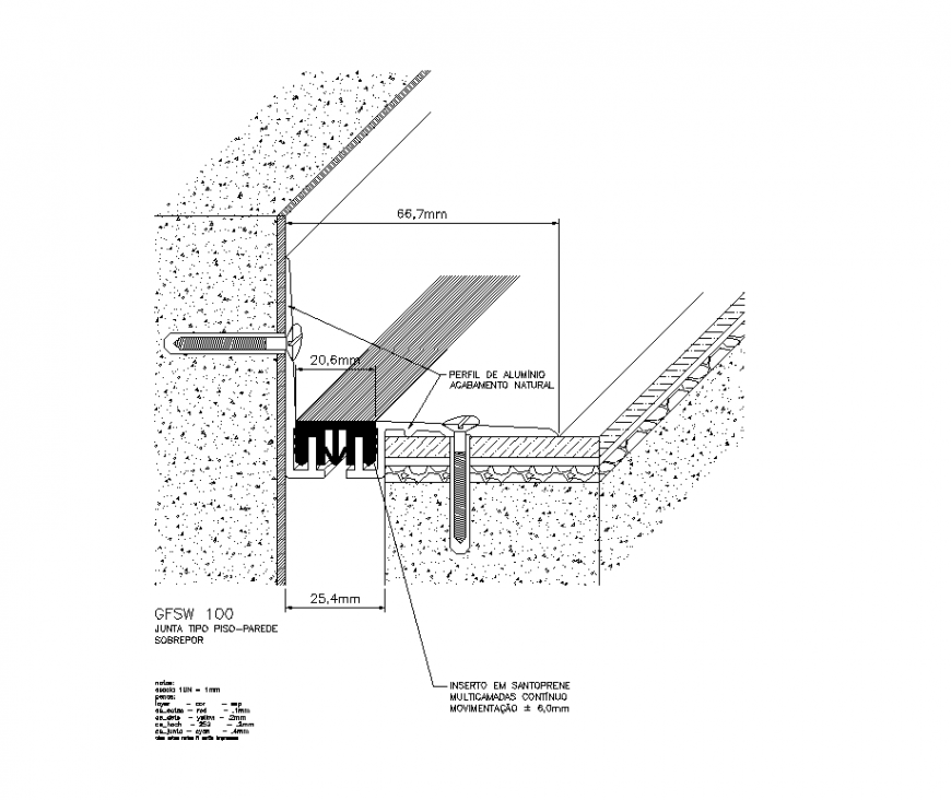
Description: Since building expansion joints are designed to isolate sections of a building, they inevitably cut through floors. Copper and copper alloys can be used in floor expansion joints in two ways: as trim and cover plates, or to prevent the flow of water through the expansion space. Copper waterstops are used to prevent the flow of water.
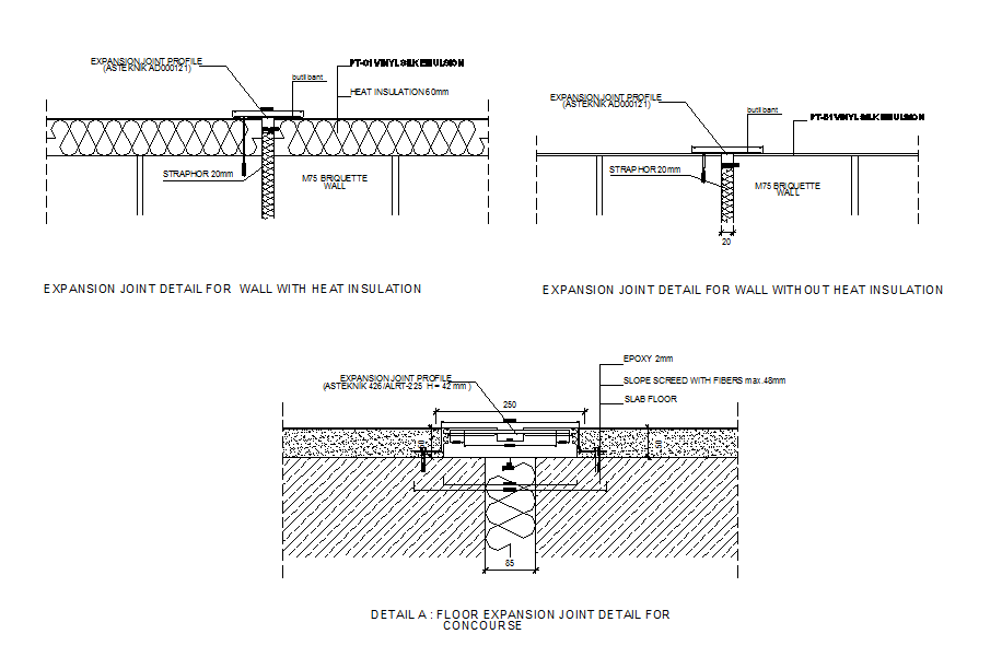
Expansion joint detail for concourse dwg file Cadbull
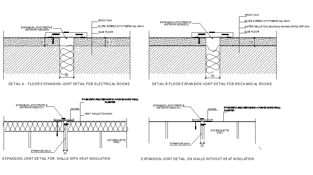
NITOFLOR - TYPICAL FLOORING EXPANSION JOINT DETAIL -T T SCALE:- NTS DRAWN BY:-DATE:- 8/8/10 LATEST AMENDMENT:- PJ DATE:- 22/10/19 TSD/F-5D03 This drawing is the copyright of Fosroc Ltd. {modified by permission) and must not be reproduced in any part without prior written permission ISSUE NUMBER 4 PARCHEM CONSTRUCTION SUPPLIES
Expansion joint detail section plan dwg file Cadbull
TYPICAL ROOF EXPANSION JOINT DETAIL Ll Ll VERTICAL WALL EXPANSION JOINT DETAIL Air Barrier Notes: 1-800-933-SIKA (7452) WWW.SIKAUSA.COM JOB NAME: DETAIL TITLE SCALE: N.T.S. VERTICAL WALL EXPANSION JOINT DETAIL DATE: FILE NO.: 03/30/2022 DRW. NO.: AB-8 AS A MANUFACTURER OF CONSTRUCTION PRODUCTS, SIKA CORPORATION PROVIDES GENERIC DETAILS AS A GENERAL GUIDE FOR INFORMATION PURPOSES ONLY. 1 ESA Publication No.011/09 (revision 2 of publication 011/01) Expansion Joints - Engineering Guide Fabric expansion joints for ducting systems Revision 1 contains change of address details for the ESA Revision 2 contains amendments to section 13.4 on Conversion factors (SI units) Wabo® Expansion Joint Systems CAD Library. Here you can find DWG and PDF files for each product we offer. The expansion component of the system may be a flexible filler material, a flexible neoprene gland or a finger joint. For details of the Department of Transport and Main Roads' approved expansion joint systems refer to the Bridge Components on the departmental website. expansion joints. In such cases, the detail-ing of joints can be difficult because the fire wall must be supported laterally. The designer is also cautioned that Fig.1 Expansion Joint Spacing Graph [taken from F.C.C.Tech.Report No.65, Expansion Joints in Buildings]. Fig. 2 Typical Expansion Joints. Modern Steel Construction • April 2005 selected, elastomeric expansion joints can handle a range of -40°F (-40°C) to 400°F (205°C) . Construction Details Elastomeric expansion joints are constructed of three basic elements: the tube, the body or carcass, and the cover . The construction details are shown in Figures 1-4 and each element is defined as follows: 1. J-SD03 Typical Floor Expansion Joint Detail. This drawing is the copyright of Fosroc Ltd. (modified by As suppliers of building and civil permission) and must not be engineering products Parchem 8 reproduced in any part without prior written permission Construction Supplies Ply Ltd do not ofer a design service. Description: Expansion joints in roofs require wood curbs around each roof area. The curbs should extend at least 8", or 10" if a cant is used, above the adjacent roof. In general, the top surface of the curbs should be sloped away from the joint, to shed condensation and moisture onto the roof. Insulation is often used in the expansion space. Expansion joint detail free AutoCAD drawings free Download 163.19 Kb downloads: 13906 Formats: dwg Category: Construction details Expansion joint detail for electrical and mechanical rooms. CAD Blocks, free download - Expansion joint detail Other high quality AutoCAD models: Expansion joint detail 2 Expansion joint detail 3 Roof Section Details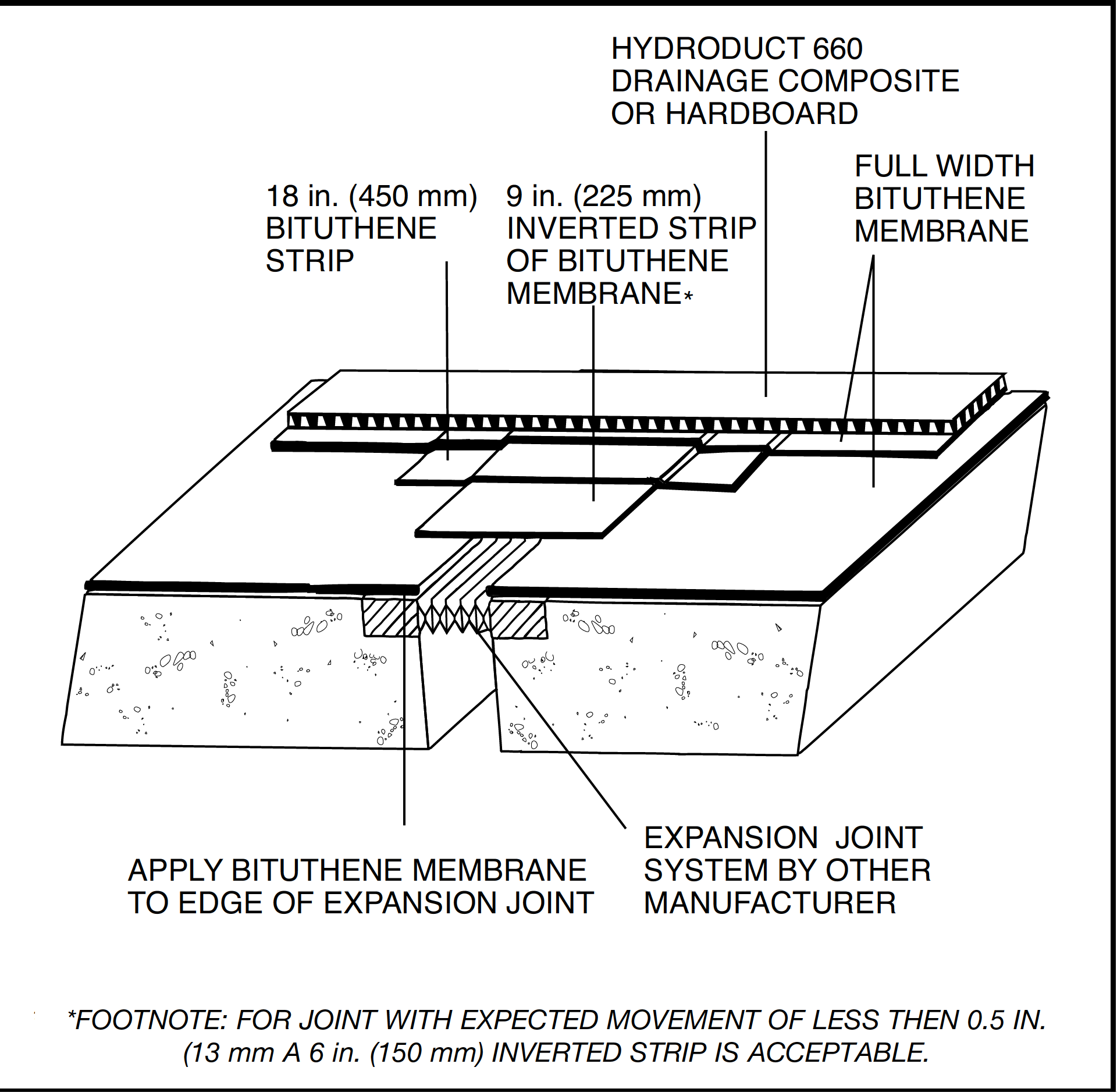
TL0011 — Expansion Joints in Concrete Construction Technical Letter Resource GCP Applied
Expansion Joint Details · BIM · CAD · DWG · DWF · EMSEAL

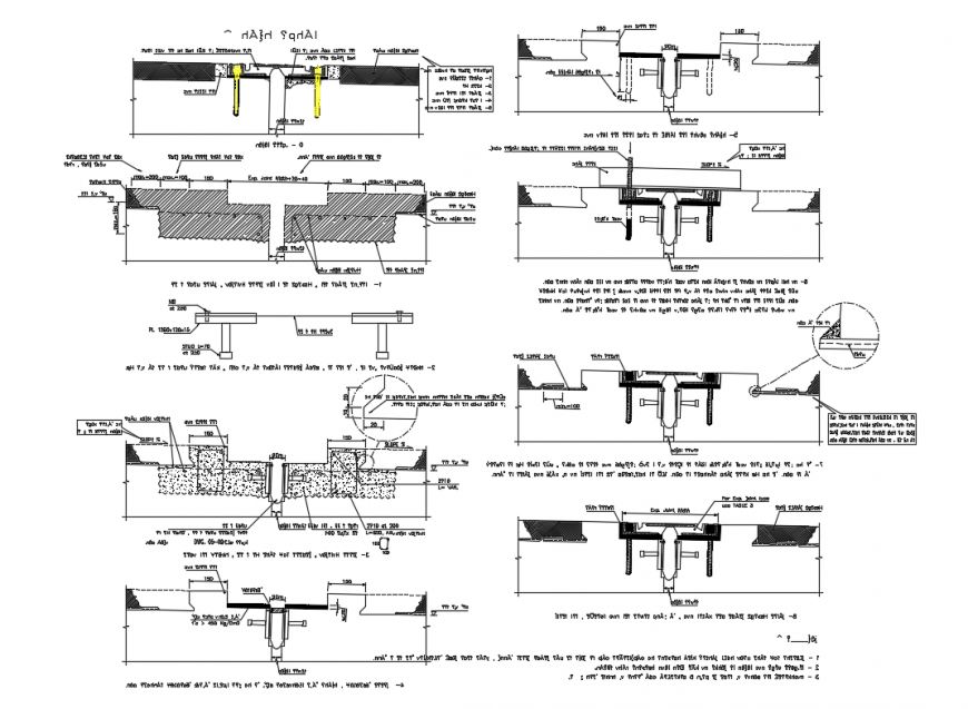
FIG. 12 TYPICAL DETAILS OF EXPANSION JOINTS AT TWIN COLUMNS OF RCC FRAMED STRUCTURES
Expansion Joint Details · BIM · CAD · DWG · DWF · Sika Emseal
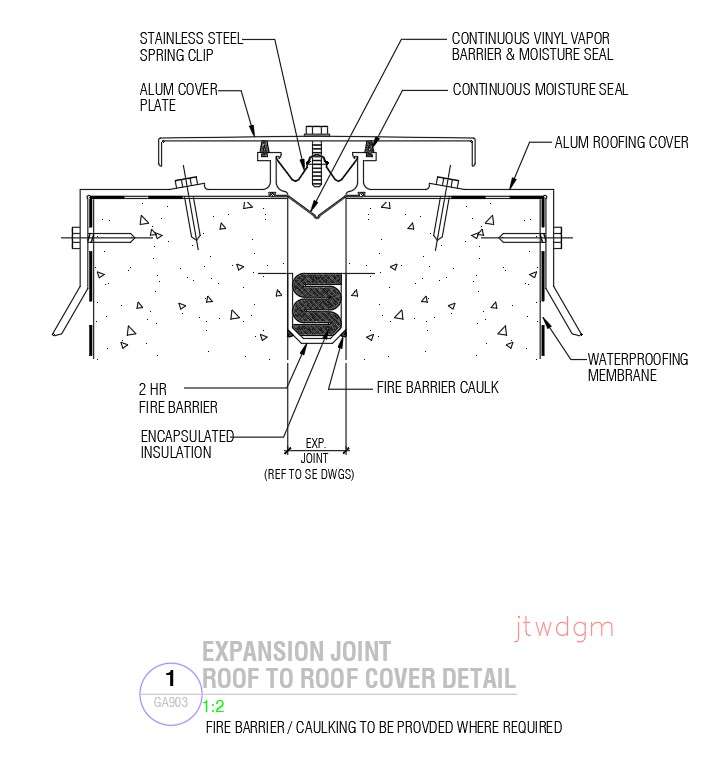
Expansion joint in roof to roof cover detail in AutoCAD 2D drawing, CAD file, dwg file Cadbull
Expansion joints details of walls of building cad structure details dwg file Cadbull
Section expansion joints plan dwg file Cadbull
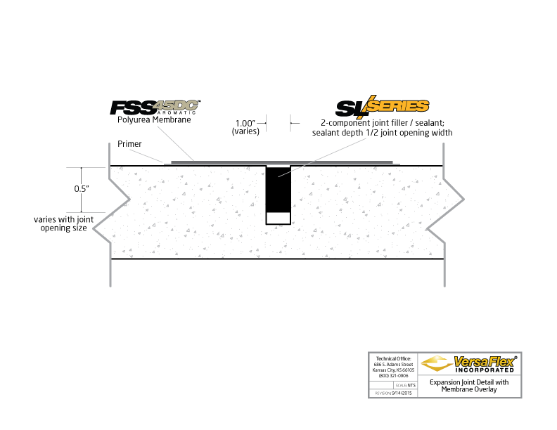
VersaFlex Expansion Joint Detail VersaFlex
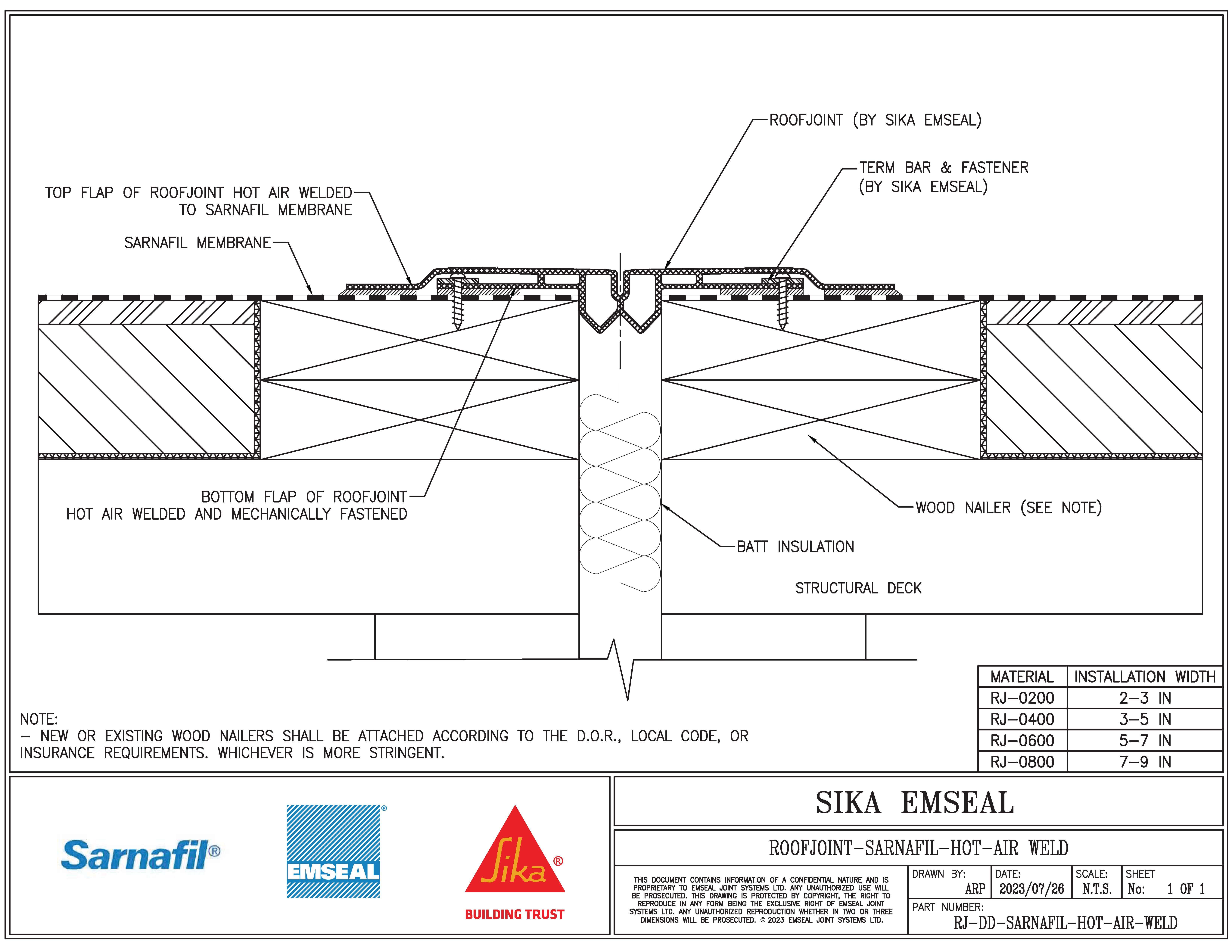
Roof Expansion Joint · RoofJoint · Sika Emseal Expansion Joints